Mechanisms
Memory
In principle, memory is capable of storing a large number of bytes. Every byte stored has a unique location called an address. If a laptop has 16GB of memory, the memory can hold 16*1024*1024 bytes. To address that many bytes there must be that many distinct addresses, so every address is (at least) a 24-bit number.
A register is made from flip flops or latches, each of which consists of at least four transistors. Dynamic Ram is an improvement which requires only 1 transistor per bit. The downside is that every bit must be read and written frequently, or it would degrade. DRAM chips have a circuit that refreshes all bits as long as they are powered. That is why normal RAM in your computer is emptied when you turn off the power.
Memory has three inputs and one output.
- One input is the control. It determines if we want to store data or fetch stored data
- The second input is an address where to fetch data from or where to store data (depending on the control)
- If the control says ‘store’, the third input is the byte to be stored. Otherwise this input isn’t used.
- If the control says ‘fetch’, the output will be the byte that was last stored at the given address. Otherwise the output isn’t used.
(In practice, bytes aren’t fetched or stored one at a time, but in larger chunks (2, 4, 8 or much more).
Loosely, fetch means the following:
- the CPU computes an (integer) address
- puts the address on the address bus
- sets a control line to indicate if it wants to fetch the data or store it
- store: the CPU puts the appropriate value on the data bus
- fetch: the CPU must wait awhile before it can read the value from the data bus
A lot of engineering concerns optimizing this naive approach. Nobody likes CPU’s to just wait.
Address ≠ Data
It is important to understand that an address is ‘just data’ until it is put on an address bus. Computing an address is just an integer computation.
For instance, to execute A[5]=1024 if A is an array in which each cell contains a 64-bit integer, then the address of cell 5 must be computed as follows
- get the current location of the first cell &A
- add to that the size of cells times the number of cells to skip
- so the location of field A[5] is address
&A + 4 \* 8
Registers
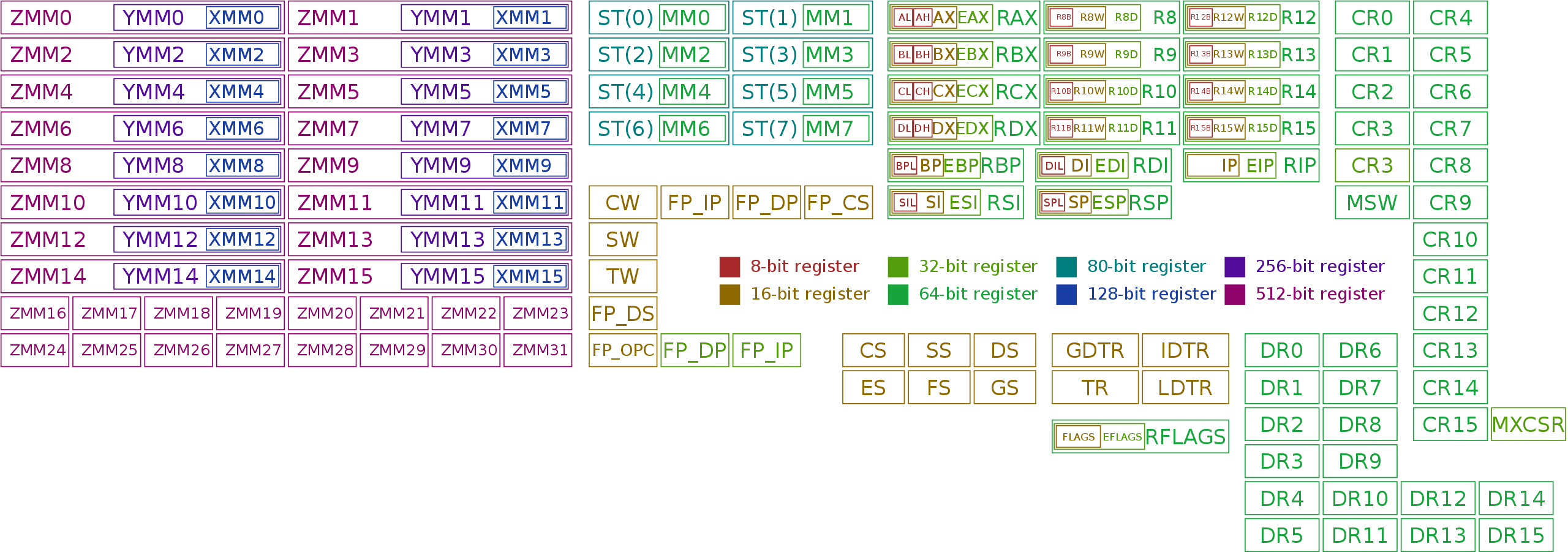
Although memory is fast, it is still too slow compared to the ALU and core operations. To achieve the best speed, registers are used. From a programmer’s perspective, memory resembles an array and registers resemble local variables.
There are two categories of registers: special purpose and general purpose registers. General purpose registers are used to compute and hold various results relevant to a program; special purpose registers hold specific values relevant for the CPU. For instance, the flag-register holds all status flags resulting from computations in the ALU (including Negative, Zero, Carry).


Source: ‘Immage - Own work, CC BY-SA 3.0, https://commons.wikimedia.org/w/index.php?curid=32745525'
Fetch-Decode-Execute
A low-level program is stored in memory as a sequence of instructions. An processor performs a fetch-decode-execute cycle:
- fetch instruction from memory
- decode to see which operation should be performed on which operands
- execute
A 6 minute overview can be found here)
Program Counter + Instruction Register
When we explain programs, we point at the code and say ‘here it does this, and here it does that’. An executing program has what is called a locus of execution: a point in the program which describes what should happen at some point in time.
A processor keeps the address of the next instruction (its ’locus of execution’) in a register traditionally called the program counter (PC – note that it doesn’t count anything).
Instruction fetch means:
- get the byte or bytes (many instructions require multiple bytes) pointed to by PC
- put the instruction is a special Instruction Register or Opcode register (IR, OPC) ready for decoding
- advance PC (ready for the next cycle)
General purpose registers allow for many different kinds of computations. For instance, the ARM instruction SUBS R8, R8, #240 takes the contents of register R8 and subtracts the value 240 from that, storing the result in register R8.
Treating the PC as a general purpose register makes sense because, many ‘general purpose’ operations are meaningful in this context.
For instance, what is the effect of the operation above if R8 is in fact the program counter? If the instruction is fetched from location here, then the next instruction will be fetched from location here-236 (next instruction after here minus 240).
In ARM this is the Branch instruction, in this case with a negative offset. The result is a loop.
A listing of x86 instructions can be found here and an in depth description of real ISA instructions can be found in Intel’s programmer’s manual (Intel® 64 and IA-32 Architectures Software Developer’s Manual) which lists all instructions including data transfer, arithmetic, logic, control transfer (affecting the program counter) and much much more.
Autoincrement
When an instruction is fetched, the PC is immediately incremented. This doesn’t take additional time; it is done by hardware in the same machine cycle.
This is an example of auto increment, which is used frequently, for example when using stacks.
Stacks
Functions are an important concept in programming. When we call a function, the current locus of execution is suspended, and we continue execution (point the locus) in the function body. When it is done, the previous locus is restored, and execution continues.
The same concept is used in a CPU: a call instruction stores the current PC and then loads a new value into it (the location of the function body).
The PC is stored in a chunk of memory called the stack which is pointed to by a register (sometimes called SP). Storing the PC uses autoincrement (or -decrement) on SP, and the return instruction does the reverse.
Functions have parameters and local variables. Where are they stored? Maybe in registers, but what if I call another function? Then my local variables must be stored in memory so that they can be retrieved when the second function returns.
A stack is also used for this. All parameters and local variables are stored in what is called a stack frame, and the stack pointer is advanced to empty space beyond the stack frame.
A special register (frame pointer) and pointer trickery is used so that the CPU (which doesn’t really know functions) can find the beginning of each stack frame.
Interrupt
When you move the mouse on your computer, that movement must be dealt with immediately. An interrupt stops a CPU core and briefly executes code to update the mouse pointer. Then the core is allowed to continue what it was doing before. A special function is activated to handle this mouse event. When that is done (perhaps a micro-second later), the core must resume what it was doing before, without any of its registers having been altered.
But what was it doing? The context of what it was doing was stored in memory, on a stack using the same mechanism as described earlier for function calls: registers are stored at the location pointed to by an SP in a frame.
Tri-State
What happens when two outputs are connected to the input of a third component. If they are both 1, do they add up and become a 2? If they conflict, does the CPU short circuit and explode?
In some technologies, tri-state outputs exist, which are 0, 1, or a third, floating state. That state can be connected to a 1 or 0 state and won’t influence it.
In other technology, a 0 isn’t grounded so connecting it to a 1 just results in a 1 output. They are OR’d together.
In modern CPU’s tri-state is only needed on external ports so that your CPU doesn’t fry when you insert a USB stick the wrong way.
Buses
Connecting the output of one component with the input of another is simple: just put a wire or metalized path in between. Connecting multiple inputs to one output is also straightforward, using a rake-shaped path. But connecting multiple outputs to one or more inputs poses a problem. What if the outputs disagree? If different values feed into one input, essentially arbitrary values are read.
A bus is a ‘device’ which solves this. In addition to the rake-shaped path it has a gate and a control line to every output. If its control is 0, an output doesn’t contribute; only the gate for which the control is 1 can output a value, which is then passed on the entire rake.
The control circuitry ensures that at most one output is passed on to the bus at all times.
Delays
How fast can a processor go? Transistors switch incredibly fast, but still require more than zero time. What limits the overall speed?
- Physical speed. Today, a CPU clock speed is about 3GHz. Time between two ticks is about a third of a nano second. In that time, any signal (limited by the speed of light) can travel about 10 cm. Since processors are tiny compared to the distance light travels even in these small time slots, signal traveling time isn’t likely to be the limiting factor (for now).
- Transistor switching speed. A signal is a current which must load a capacitor (such as the gate in a transistor) and overcome resistance in order to switch. But the switching time of modern transistors is on the order of picoseconds. Single transistor switching time isn’t the limiting factor.
- Sequencing. Consider the N-bit adder consisting of a half-adder for bit 0, and N-1 full adders for the remaining bits. Each full adder takes the carry of the previous addition and uses it in its own calculation. In a 32-bit ripple-carry adder the tiny delays before each carry is valid adds up. (Note that carry-lookahead is a typical system-engineering approach to reduce this delay)
The tiny delays become a problem when considering stateful components such as latches. When a latch is set its input should be valid, but how is the latch to know?
Clocks
A clock is a crystal-based component that gives a pulse every so many nanoseconds Components use the clock to know when they can use the output of other components.
Circuitry is used off of a clock to create other clocks:
- A delay creates a clock with the same frequency but different phase
- A divider creates a clock with lower frequency
- A multiplier creates a clock with a higher frequency. Most processors use a clock of a few hundred MHz with a multiplier to reach their desired running speed
A clock grid transports the clock pulse across the entire CPU so that all components can use it with the least possible delay.
Flip-flops & Latches Revisited
A flip-flop is changed when the control line is high. A latch is changed only when the control changes, from low to high. The purpose is the same (storing a bit) and the context determines what type flip-flop or latch is appropriate.
The ability to choose allows us, for instance, to perform a calculation when the clock is high, and to capture the result when the clock changes to low.
Clocks and precise timing are outside the scope of this writeup.
