Components
Adders
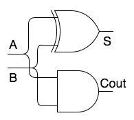

A half adder is a component which adds the right-most bits of two numbers. It takes two inputs and produces two outputs: the sum and the carry. Note how the component does the same as we do when we add two numbers!
A full adder is a component which adds other bits of two numbers. It takes three inputs (two operands and the carry from additions to the left) and produces two outputs: the sum and the carry.
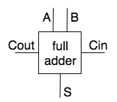

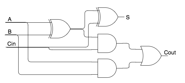

For obvious reasons trivial components such as one bit adders are often drawn as components (not showing the gates).
Larger components
From these parts larger components can be created. This is an N-bit adder, made from one half-adder and (N-1) full adders.


In general, any component can be designed by breaking it down in Boolean functions, truth tables and gates.
Decoder
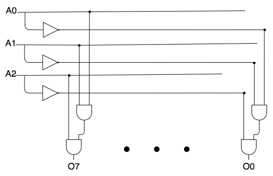

A one-of-eight decoder uses three address bits to set one of eight bits on (and the rest off). For instance, decode(1,0,0) => (0,0,0,1,0,0,0,0). Bits are numbered as usual from right to left starting with 0, so 100 (= 4 decimal) addresses the fifth right-most bit.
Each of the output bits turns on for one specific combination of input. For instance, o(5) = i(1) AND NOT i(2) AND i(3). From this observation, designing the circuit is straightforward.
⊙
Exercises (Encoder) (click for solutions!)
- o(2), the high-order address bit, is only set if one of the high-order input bits is set, so:
o(2) = i(7) OR i(6) OR i(5) OR i(4) - o(0) is only set if one of the odd-numbered inputs is set:
o(0) = i(7) OR i(5) OR i(3) OR i(1) - And the last when odd pairs are set:
o(1) = i(7) OR i(6) OR i(3) OR i(2)
The design using gates is now trivial.
An encoder does the reverse: given inputs one of which is 1 (and the others are 0) an encoder produces the address of the set bit.
- Design an 8 to 3 encoder
⊙
Exercises (Encoder) (click for solutions!)
o = (a AND c) OR (b AND NOT c)
A multiplexer is an important component which uses one or more controls to copy one of two or more inputs to the output.
A 2-input multiplexer is implemented by the trivial equation for inputs a and b, control c and output o. The circuit follows trivially from the equation.
- Design a 2-input multiplexer.
This idea can be extended to
- more than 1 bit wide inputs
- more than two inputs (requiring more than one controls)
- ‘output multiplexing’
Note: a demultiplexer is a component which allows us to copy one input to two or more outputs, based upon controls.
Note: a multiplexer can also be made using a decoder by AND-ing each decoder output with one input.
Flip-Flops, Latches
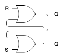

Not all components are Boolean functions. Flip-flops and Latches are components which maintain an internal state (0 or 1): they are one-bit memories. CPU registers are built from flip-flops and latches.
The simplest form is an SR latch, which has two inputs S and R and two outputs Q and Q. If S and R are 0, either Q or Q will be 1 (and the other 0) depending on the current state. When S is 1 (and R is 0) the state is set. That is, Q will be set forthwith. When R is set (and S is 0) the state is reset (Q=1, Q=0). S and R should never be 1 at the same time because then the output will become unreliable.
Many other flip-flops and latches exist, such as a D-latch which has a control (C) and a data input (D). The internal state is set to D only when C is 1 and is unaltered otherwise.
Flip-flops & Latches => Registers
Flip-flops and latches (we’ll discuss the difference later) can store a bit which can be read or changed using control lines.
Putting flip-flops or latches in a row of 8, 16, 32, 64 or more bits makes a logical component, which is called a register and which stores a value: an integer, a character, a float, an address.
